Smartphone Garage Remote | 02 | Circuit Design
Remembering the functionality chain from before, the physical connection between the Raspberry Pi and garage remote will be the most involved. The other connections are either already established or will be established with relative ease.
Simple Configuration and Shortcomings
My initial plan was to use a couple simple and straightforward connections in order to link the remote to the Pi. The button on the remote would be short-circuited such that it would activate whenever powered. The battery is removed and the empty terminals are connected to electrical ground as well as a GPIO ("general purpose input/output") pin.
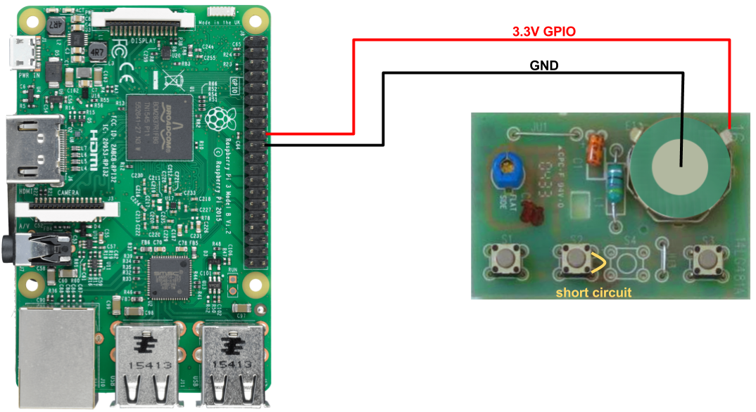
Unfortunately, this approach would work on occassion, but not consistently. After long periods of inactivity (i.e. overnight) the system would need two activations to function properly. This is likely due to the capacitors losing charge over time without a consistent supply of power. In order to avoid this issue, we need to use a more traditional switching circuit in which the remote is given a consistent supply of power, and the switch is wired through a switching circuit.
Switching Circuit Configuration
There are many pre-built switching circuits that can be purchased for the Raspberry Pi that would make this particular challenge relatively quick and easy. However, my intention is to learn, understand, and apply myself, and therefore, a pre-built solution would defeat the purpose of this project.
This more complex circuit will provide power to the remote at all times via the 3.3V power pin on the Pi. The switching will be accomplished by an NPN transistor. Transistors allow current to pass between the Collector and Emitter if provided with the appropriate Base voltage. In the case of an NPN transistor (as opposed to a PNP transistor), the channel between the collector and emitter will normally not allow current to flow. Only when voltage is applied to the base will current flow between the collector and emitter.
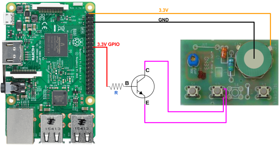
In addition to the transistor, a resistor is required to limit the current flow out of the Pi's GPIO pin. The specific calculations are in the following section.
Circuit Calculations
While the 5V pin on the Raspberry Pi provides power directly through the micro-USB port used to power the Pi, the 3.3V ports and GPIO pins rely on the internal circuitry of the Pi. Therefore, these ports must not exceed certain limits. Specfically, each port can provide only 16mA of current, and in total, all ports can provide only 50mA at once.
Using a multimeter, it was determined that the remote requires 3.2mA of current at 3.2V, thus it is safe to power it via the Pi's 3.3V power port.
After analyzing the switch it was determined that when the switch is open, there is a 2.85V differential across the gap. When the swiched is closed, 0.1mA of current will flow across this gap. These values are important in determining the transistor requirements.
First, we must determine if our transistor can handle the current through its C-E channel. Our load is a very small 0.1mA, and our chosen transistor (NTE47) can handle 200mA of continuous current. The voltage requirements pass as well; the 2.85V differential is much less than the 45V our transistor is capable of handling.
Next, it is easy to see that the transistor is capable of switching the 0.1mA current from a possible base current. The $h_{FE}$ value of the transistor provides the ratio between the C-E current that is allowed by a B-E current. Seeing as how our Raspberry Pi can output a maximum of 16mA of current from one pin, supplying enough current to B-E such that it can switch 0.1mA at C-E is possible regardless of the $h_{FE}$ boost.
Our final consideration is limiting the current flow out of the Pi's GPIO pin into the base of the transistor. This can be accomplished with a resistor between the two. Our upper current limit is 16mA, so we must find a resistor that will limit our 3.3V output to a lesser amount. I happened to have some 470Ω resistors on hand, and by wiring them in parallel with one another, we end up with half the resistance at 235Ω. Using Ohm's law, we can see that a 3.3V source passing through 235Ω of resistance will be limited to 14mA.
With these calculations, we can be certain that our switching circuit can successfully switch the remote on and off in a way that is safe for both the remote and the Raspberry Pi.